HOW A STEAM LOCOMOTIVE WORKS
THE BASICS
James Watt noticed that when water is heated to boiling point that the steam produced could be made to be useful, such as to drive a wheel. This is simply a means of converting one form of energy (chemical) to another (kinetic). The fundamentals for effecting this are a closed container for the water (boiler), a source of heat (firebox) and a means of converting the steam pressure to angular momentum (pistons).
THE COMPONENTS
Firebox
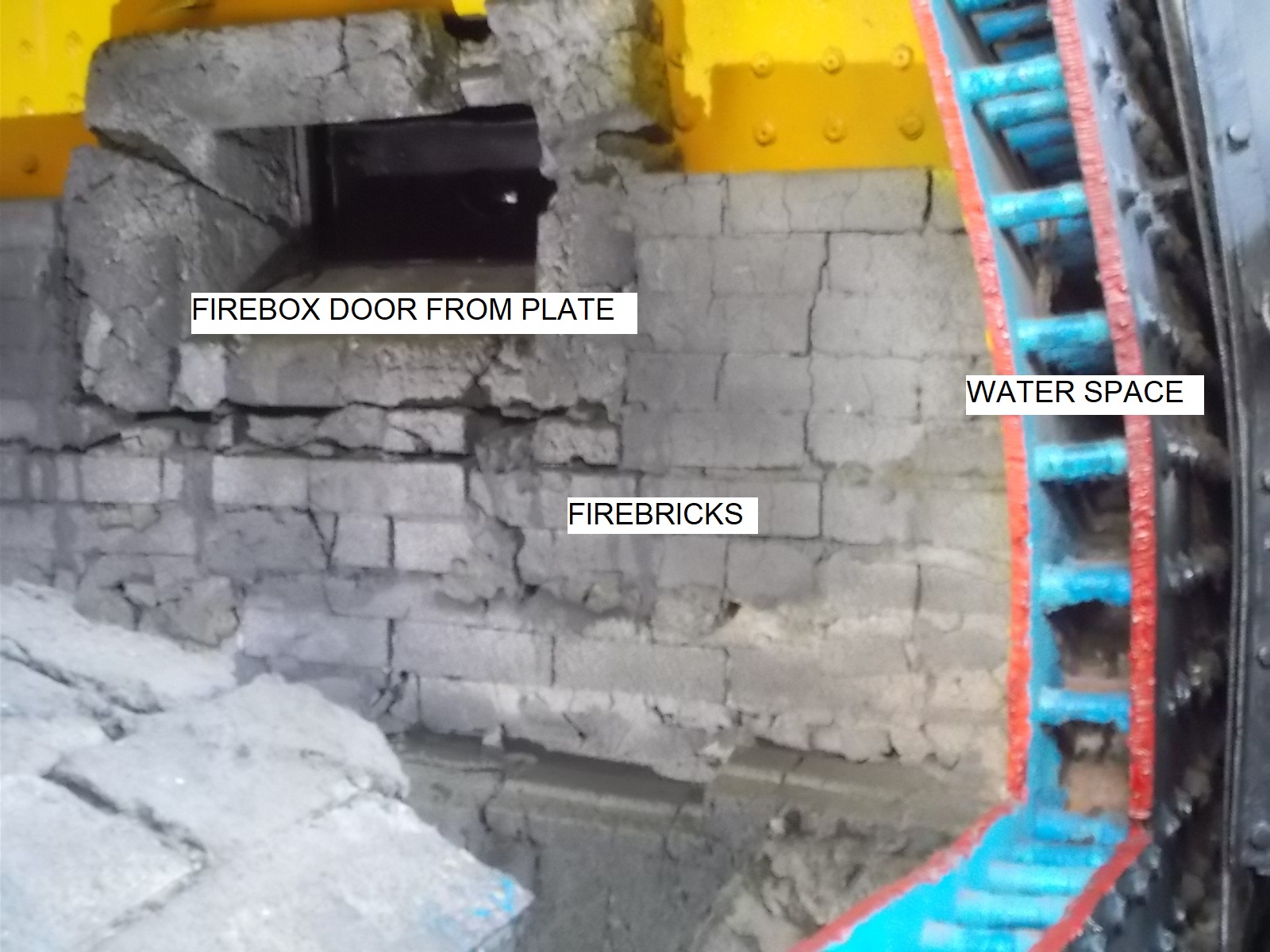
Looking at the above image, we can see on the right the cab and then the firebox. This is where the heat is produced to bring the water to boiling point to produce steam. Fuels used can be coal, wood, gas, oil or electricity.
Boiler
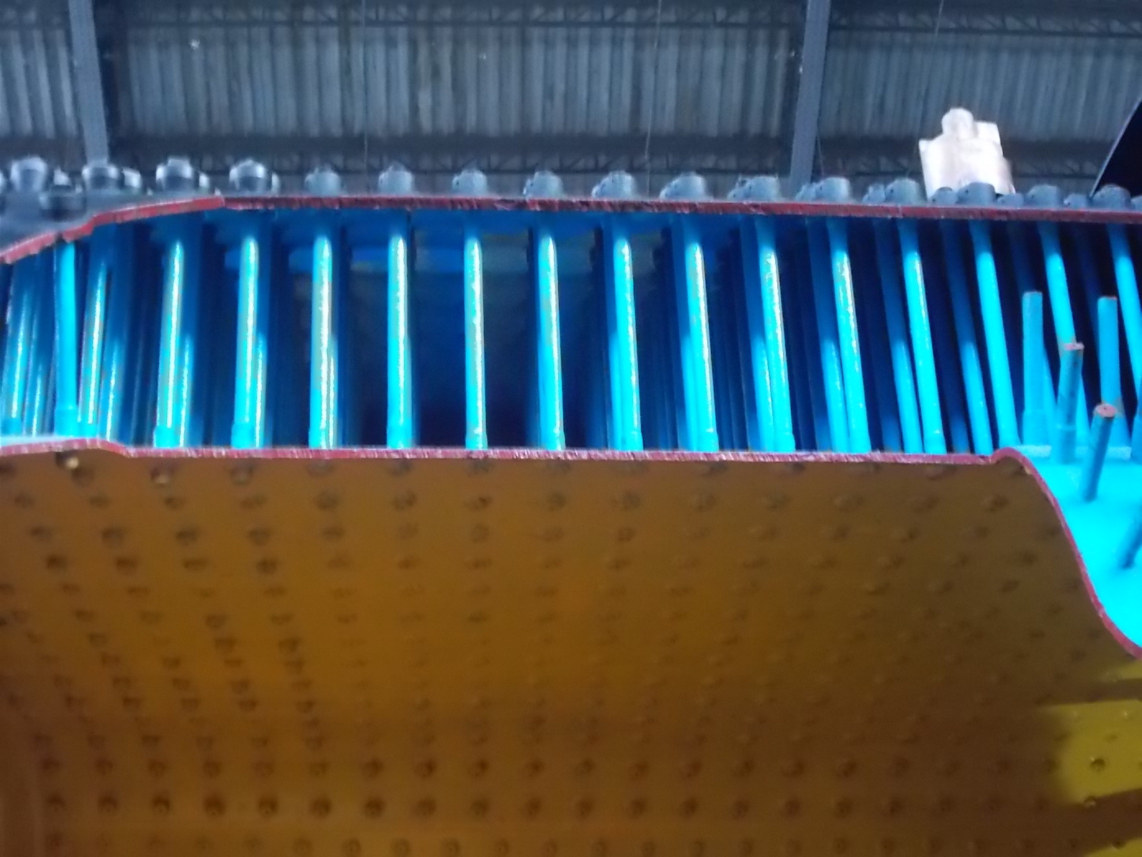
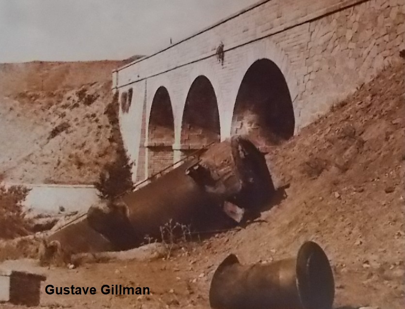 The boiler is to the left of the firebox in the first photograph and the whole area in blue would be filled with water with a space above it. The main problem is that water has a high coefficient of heat which means that it takes a lot of heat to bring the water to boiling point. Then to convert the water to steam requires five times the energy to heat the water from 0°C to 100°C to overcome the latent heat of evaporation. Just lighting a fire in the firebox wouldn't be sufficient to produce enough steam to propel the locomotive due to the small surface area of the firebox. Thus, the heat is drawn through pipes that pass through the boiler. It is also vital that the water in the boiler must always cover the top of the firebox as the heat produced in it can reach a temperature of 1,400° Celsius. Without the cooling effect of the water, the steel will buckle and a catastrophic boiler failure could result. Why catastrophic? The boiling point of water is 100°C at sea level but increases to nearly 200°C in a fully pressurized boiler at nearly 20 Bar. If there is a boiler failure, the sudden release of pressure is serious enough but after the steam is released there remains tons of water that boils explosively as the pressure on that water is relieved. This has resulted in spectacular explosions in the past, including one on the GSSR near to Tíjola.
Smokebox
The smokebox, as the name suggests, is where the smoke from the firebox collects and which then passes out through the chimney. On its own, this wouldn't happen without a drawing effect which is effected by passing steam vertically through the smokebox, thus causing a suction effect.
Regulator
The regulator is the means for the driver to control the power of the loco and thus its velocity. This is essentially a valve that controls the amount of steam going to the pistons.
Valve gear
The valve gear is spectacularly complicated as it has to control the flow of steam to each side of the piston depending on direction of the train, velocity and power.
Cylinders & Pistons
The pistons convert the steam pressure to kinetic energy to drive the wheels. Steam enters each side of the cylinder depending on the position of the piston/direction of travel.
Drive shafts
These link the pistons to the drive wheels transferring the force into traction to propel the train.
Tender
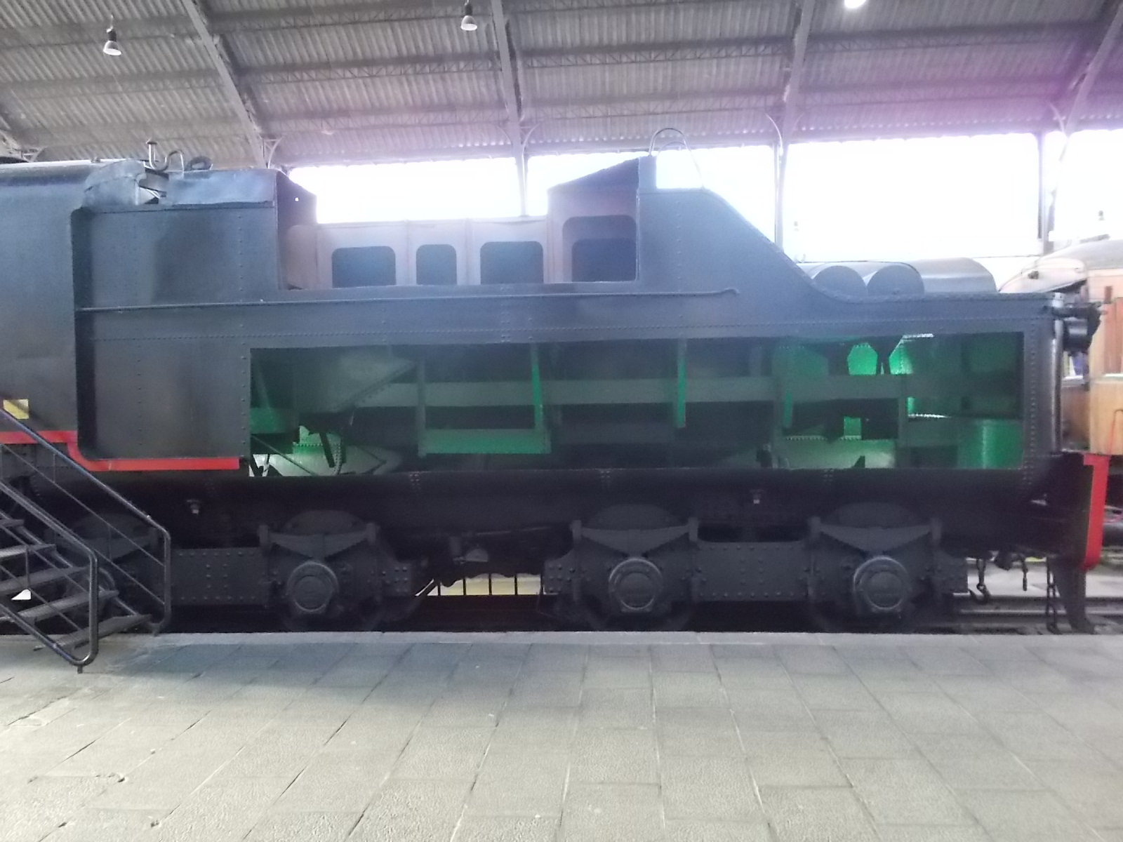
The tender carries the combustive material (e.g. coal) and the water needed to propel the loco. The water tank is below, and the coal on top.
IN DETAILTHE COMPONENTS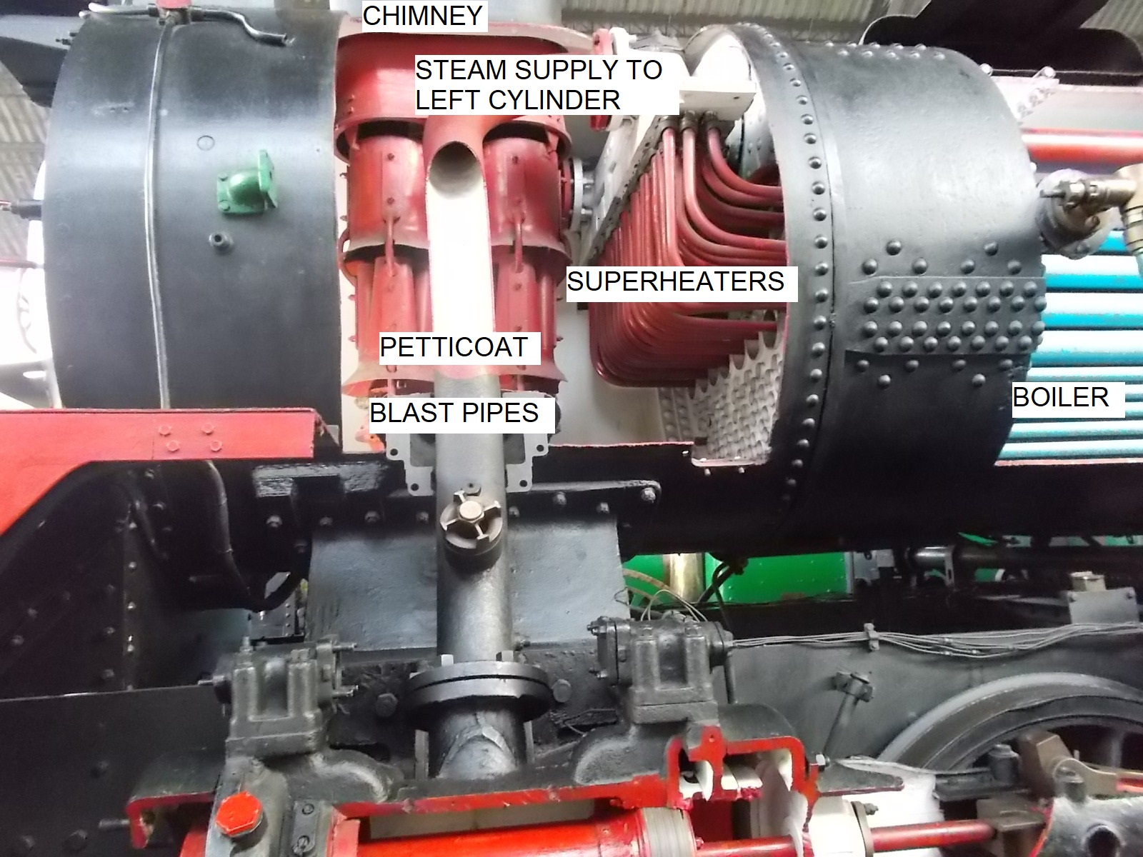 FireboxThe firebox is the core of the loco and the only source of heat for the production of steam. The walls are protected by firebricks to prevent the steel buckling, except where the firebox is in direct contact with the boiler water. There is a door for the fireman to load e.g. coal and the floor has a mechanism for clinker and ash to fall down to the ashpan. The greatest danger to a boiler is for the water level to drop below the top of the firebox thus causing it's roof to buckle and then fail, causing a catastrophic explosion. |
 BoilerThe boiler converts the enormous heat from the firebox into steam under high pressure, which can be up to 260psi. |
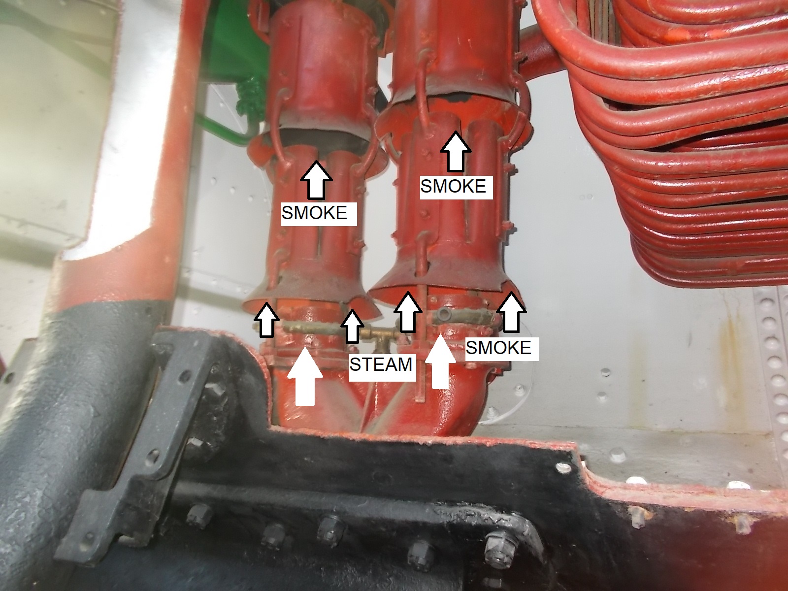 The smokeboxThe smokebox is not just a chimney. As well as being the receptor for all of the smoke and excess heat from the boiler, it is also responsible for drawing the same smoke through the boiler tubes. This is done by blowing steam up through the firebox via jets which draw the gases up with them. This is accentuated by placing a jet below a cone-shaped tube (a petticoat) resulting in the draw of exhaust gases up through the chimney. In addition, the smokebox was where access to the boiler was effected. Therefore, it had a hinged door at the front of the loco which could be opened for maintenance. |
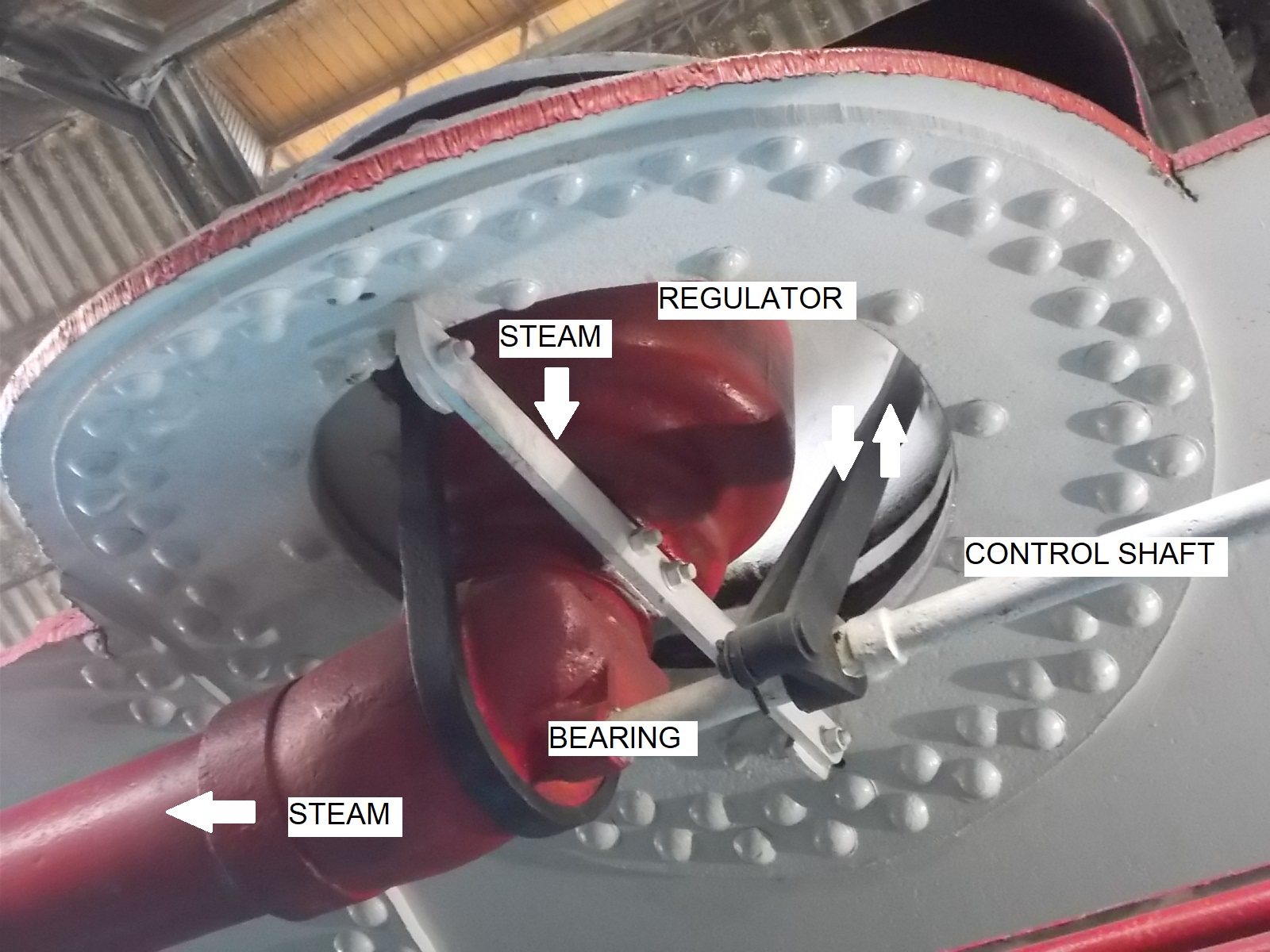 RegulatorThe regulator is essential to the control of the loco. It is where the steam from the boiler is released to the cylinders in a controlled way. It is placed in a dome on the top of the boiler to reduce the risk of water bubbling over and entering into the system. There were many designs of regulator valves, each having benefits and drawbacks but they all did the same thing, the control of steam pressure to the cylinders. |
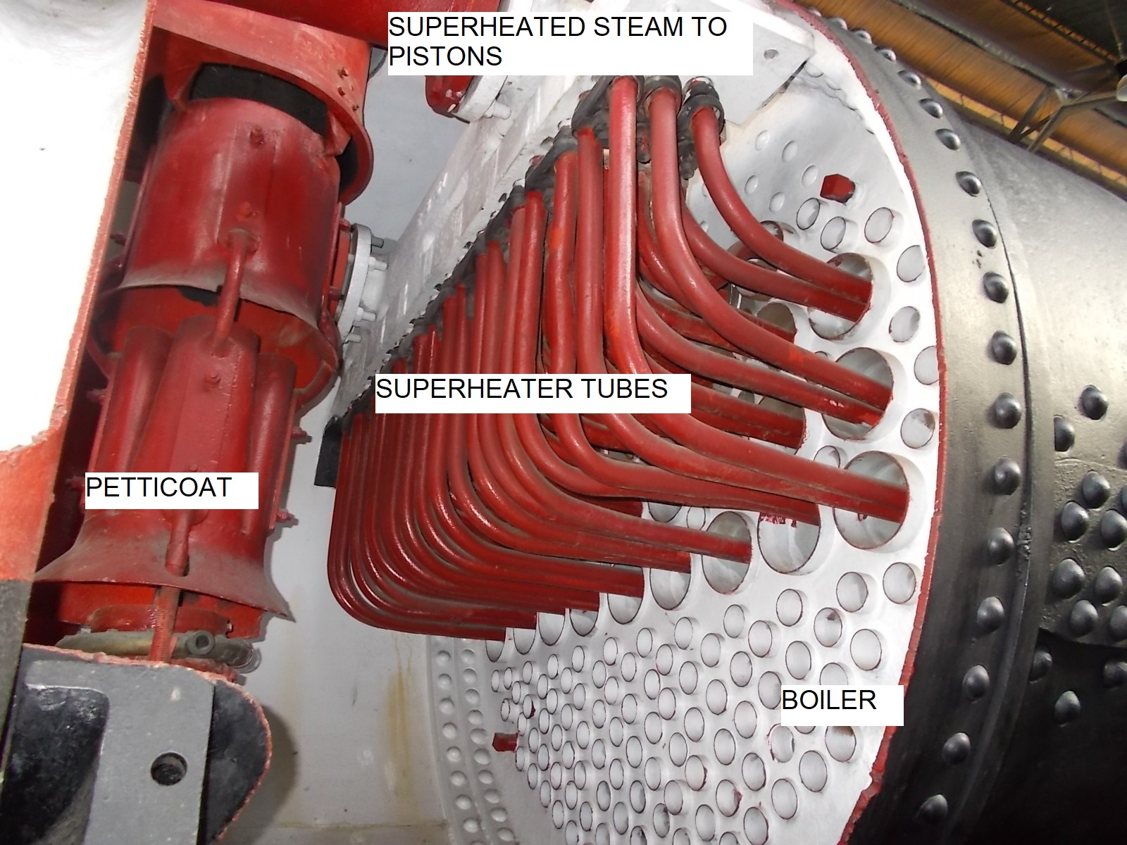 SuperheatersIf steam is heated above the temperature of that in the boiler, the locomotive becomes more efficient due to the further expansion of the vapour. Also, the additional temperature of the steam means that it is less likely to condense in cylinders or intermediate tubing. Thus, the steam from the boiler is passed through the superheater tubing and hence via a header to the valves and the cylinders. |
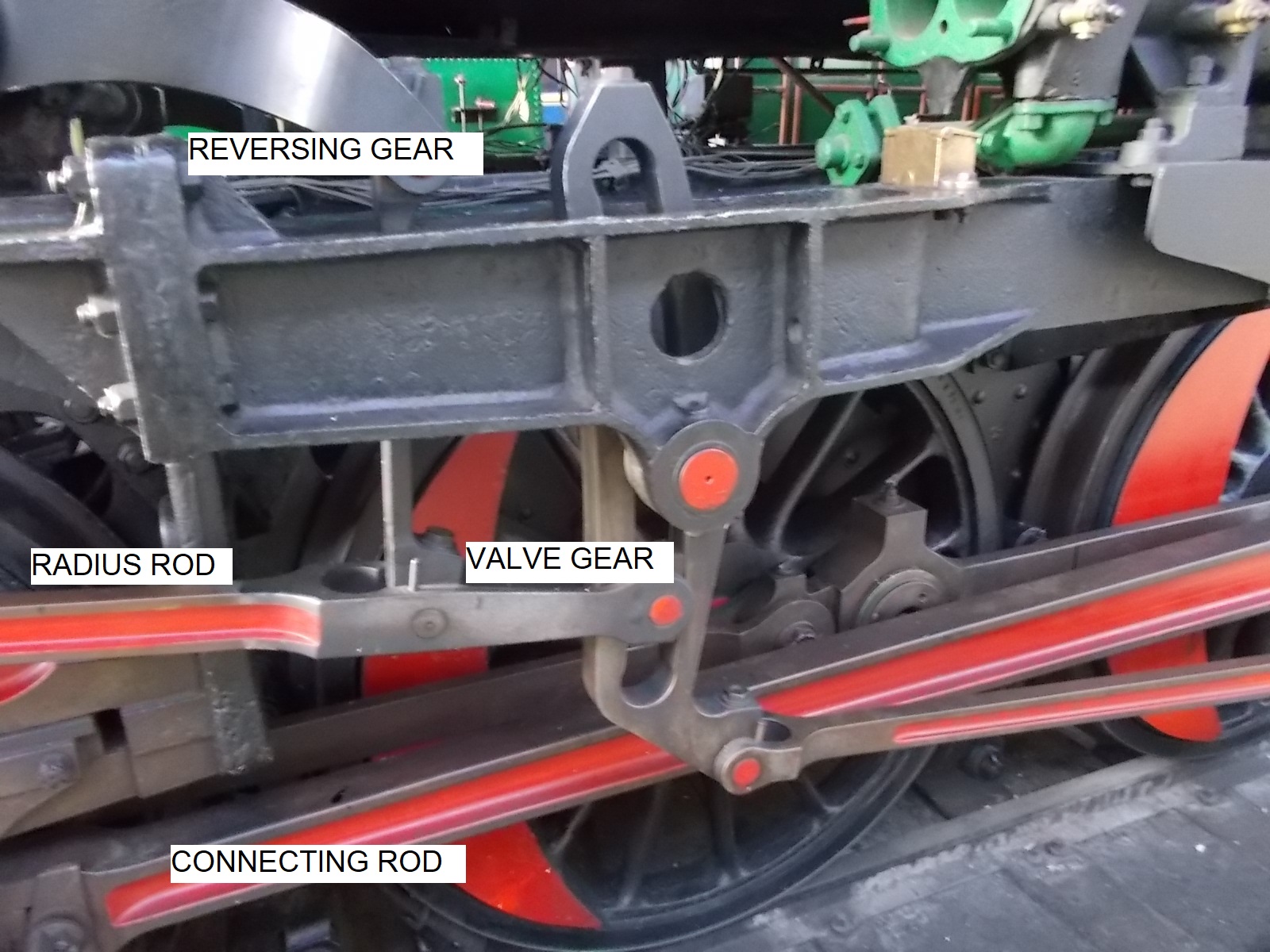 Valve gearThe valve gear is probably the most complex and difficult to understand part of the loco. This is due to the requirements put upon them. When the train is stationary, it is necessary to initiate movement in either the forward or reverse directions. In addition, the steam from the boiler has to be injected into the cylinder in synchrony with the position and speed of the pistons/wheels. To effect this there is a complex structure which is designed to cause the valve to distribute steam to either side of the piston when needed. Essentially, the valve gear is a mechanism that is driven by the wheels and which can be adjusted easily so that the amount of steam being provided to the piston is co-ordinated depending on the position of the piston and the wishes of the driver. This system allows a loco to start from stationary, to go forward or reverse, and to brake. Whole textbooks have been written solely on the subject of valve gears due to their complexity. Walschaert invented a valve gear that would take advantage of the function of steam whereby it expands inside the cylinder by closing the valve early. This results in extra efficiency. |
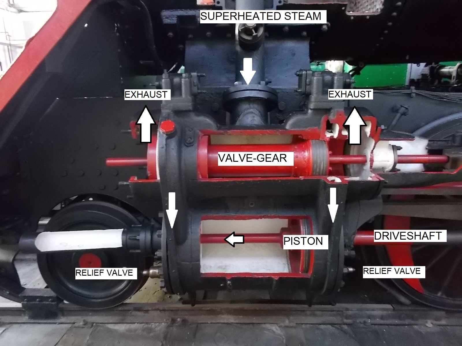 Cylinder & PistonThe piston is directly connected to the drive wheel(s) via bearings so that the reciprocal effect of the piston drives the train. To do this, steam is alternatively supplied to either side of the piston. The piston and shaft has to be precisely aligned so that there is no movement out of true which can cause excessive wear on the piston rings and cylinder bore, and to this end, there are slider bars which maintain the alignment of the drive shafts. The piston rings are made from hardened steel, similar to those found in a car engine. The main risk to a piston is water that has come down from the regulator or from condensation in the system. As it is incompressible, if found in the cylinder, it can cause a catastrophic failure. To ameliorate this, relief valves were installed on the ends of the cylinders. To the left of the piston in this image is a tail-rod (inside the cylinder in this image). These were fitted in the mistaken belief that they would prevent excessive wear on the pistons/bores. The exhausted steam under reduced pressure is sent back via the valve gear to the smoke box and chimney to draw smoke from the firebox through the boiler tubes. |
 Drive ShaftThe drive shaft chain transfers the kinetic energy from the piston to the wheels by means of a drive shaft, connecting rods and bearings. Due to the excessive loads on the bearings, they need to be constantly lubricated (see lubrication). By necessity, the drive shaft is rod shaped to be able to pass through the end seal of the cylinder end and also needs to be as small as possible thus necessitating a high quality steel. Vertical movement is restricted by sliders to prevent the drive shaft from moving in the vertical plane. |
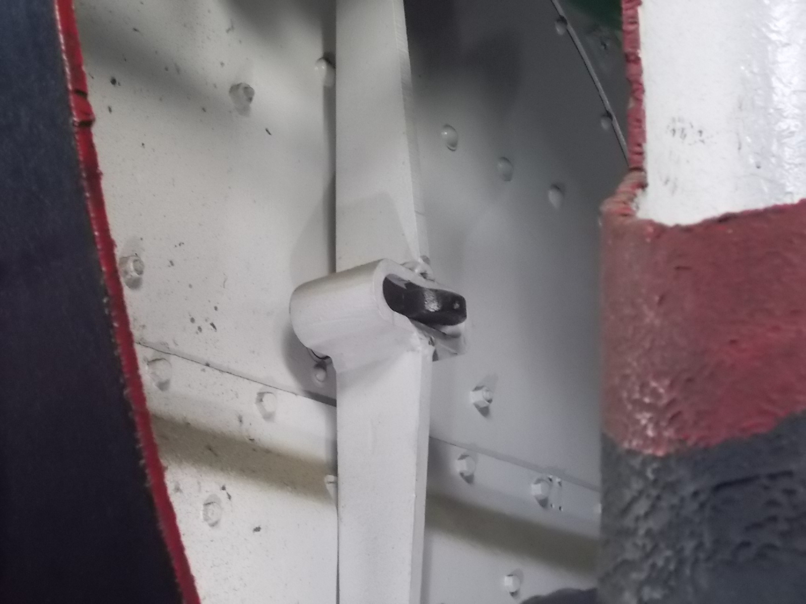 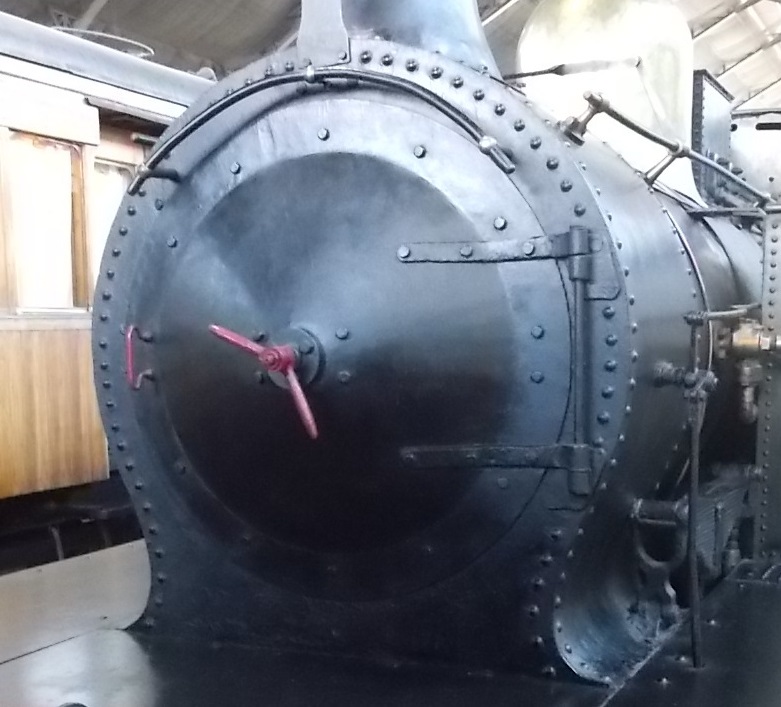 Boiler doorSteam engine boilers require regular maintenance such as inspection of the tubes, superheaters, regulator etc. To this end, the front of the boiler has a hinged door which is re-inforced by a brace and bolt which passes through the centre of the door. There is a double wing nut on the front which is what gives the front door the impression of a clock. The reason for this is that the smokebox is under reduced pressure due to the blast pipe drawing gases up through the chimney. If there are any leaks in the door, the efficiency of the locomotive will be compromised. |
LubricationIn the past there was not the range of lubricants such as are available today. Thus the bearings needed to be lubricated at every stop of the train. On long distance locomotives, this was impossible so oil feeders were designed to keep bearings lubricated. In addition, greases were used but the main problem was finding lubricants that could withstand temperatures of around 400°C. |
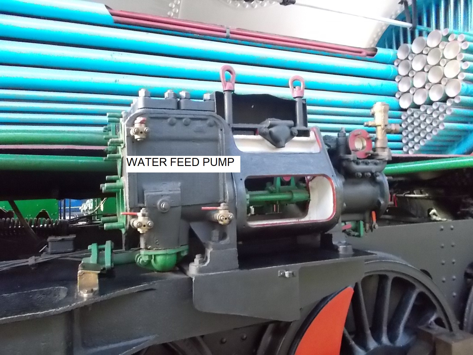 Water feed pumpDuring even a short journey, it was necessary to maintain the level of water in the boiler by replacing that which was converted to steam. This meant that cold water from the tender or the side tanks would have to be forced into the boiler at a higher pressure than that of said boiler. There were two methods for this, each with their problems. The first to be used was that of a reciprocating piston or a turbine driven from the drive train. Later, a steam system was used where steam was passed through a jet inside the water causing water to be drawn into the boiler in a similar way to the smoke being drawn up through the chimney. The flow of water was controlled by the driver. To ameliorate issues with cold water damaging hot boiler parts, a system of baffles was usually used so that the cold water didn't impinge on one area of the boiler. |


